Chickens Are Automatic
They may be the easiest backyard animal to care for. They get up in the morning, do their days activities, and then put themselves back to roost at the end of the day. During the day they scour the yard looking for bugs, worms, berries and other things to eat. They then convert these things into fresh eggs. They may need additional food and water depending on what they can find in the yard, but they definitely do need some help with security. Mainly, they need a secure place while they’re sleeping. This is typically accomplished with a chicken coop with a door to keep out predators.
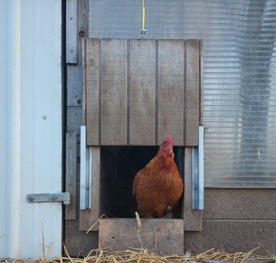
A chicken coop door is necessary but it doesn’t have to be automatic. Our vertical sliding door on a string has worked for years with no problem. The inconvenience comes when we are away from home and have to make arrangements with our neighbor to care for the chickens – morning and evening. Or, when we forget about the door and have to go out to the coop and close the door late at night or risk an unwanted visit from the pillaging horde of raccoons in the area. The automatic chicken coop door in this article is powered electrically, actuated by the amount of sunlight, and will open and close the door on the chicken’s schedule. The door goes up in morning and down in late evening, just like a chicken. It’s not too complicated and makes a great DIY project.
Build vs. Buy
Although this is a great DIY project with several options which can be customized to your particular coop and door needs, there are also readily available automatic doors that just need to be attached and set up according to the instructions. That may make sense as the better solution for some.
Building one does take more time and may actually end up costing as much or more, but it also allows flexibility in design and location.

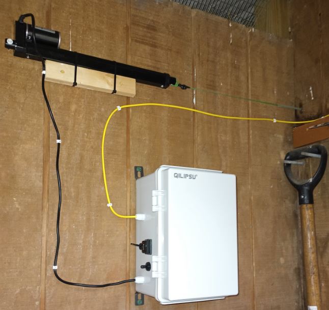
The type of automatic coop door in this article uses a handful of readily available parts as described below and in the materials list. The movement comes from a 12 volt DC linear actuator with a 12″ stroke. The actuator is remotely located from the door and it’s attached to the door with a section of nylon weed trimmer line. Other flexible attachment means can work as well, such as cable, string, rope, chain, fishing line, etc. Flexible attachment, as opposed to a rigid attachment, prevents the guillotine possibility when the door is closing. Power comes from a 12 volt DC source. This could be a 12 volt power supply, a solar charged battery setup, or in our case, a rechargeable tool battery. Or, you could set up the power to be a combination with a manual switch or some type of automatic control to toggle between power sources. It just needs to be 12 volts DC and able to supply enough amps to power the entire control.
Ours draws about 0.6 amps (600 mA) when the relay is energized and the actuator moving. The actuator moving only happens during the open and close movements which is about 1 minute total per day. During the daylight time the amp draw is about 0.045 amps (45 mA) which is the control relay and voltage cutoff device load if using the tool battery power option. More about that later. In addition to the 12 volt tool battery, we’re also using a 1.2 amp AC adaptor left over from some long forgotten electronic device.
Modes Of Operation
Dark Mode
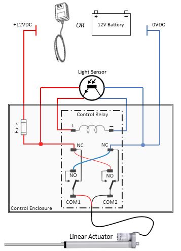
When its dark outside the light sensor does not pass the 12VDC to the control relay. This is the state shown above and is the position of the relay contacts with no power applied to the relay. The normally open (NO) relay contacts remain open. The normally closed (NC) relay contacts remain closed. This applies the +12V to the actuator red wire and 0V to the black wire. With this polarity the actuator extends and closes the coop door.
Note: The advance/return action in relation to the voltage polarity may vary between actuator manufacturers.
Light Mode
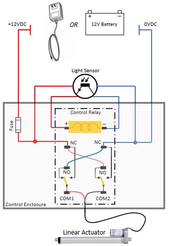
When its light outside the light sensor does pass the 12VDC to the control relay, energizing the coil. The normally closed (NC) relay contact will open. The normally open relay contact (NO) will close. This applies the +12V to the actuator black wire and 0V to the red wire. With this polarity the actuator retracts and opens the coop door. This state is shown in the diagram below.
The Control Relay – The Heart Of The Control
There are several relays available for the control of the actuator, but the Phoenix Contact model mentioned in this article draws less current, therefore uses less power, than several other types we’ve tested. It is the heart of the control and worthy of some detail comments.
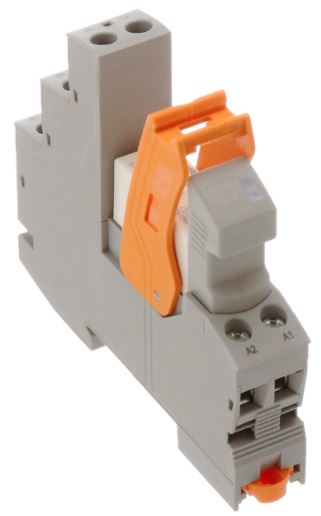
First, this relay draws about 1/10th the amps of the ice cube style relay originally tried. This Phoenix Contact relay is a type found in industrial controls and is a well made component. I didn’t find this one on Amazon but it was just as easy to purchase on the Newark website and arrived quickly However, no free shipping on this one.
Link to Phoenix Contact DPDT relay
NOTE: This relay does require DIN rail for mounting. I used the short section that came with the ice cube style relay from Amazon.
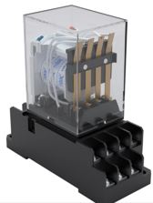
The ice cube relay drained my little 2 amp hour battery in less than a day. The power draw is not a huge deal if using an ac adaptor as the 12 volt dc supply, but it is a concern if using a battery as the 12 volt dc power source. This style relay is available from Amazon as well as other online sources.
Link to Ice cube relay.
Whichever relay you choose it needs to be a double-pole double-throw (DPDT) relay. DPDT means it will switch the two sets of contacts in a manner that will allow the actuator polarity wiring to be reversed allowing the advance/return motion. And, it needs to have a 12 volt DC coil.
The Light Sensor – The Brain Of The Control
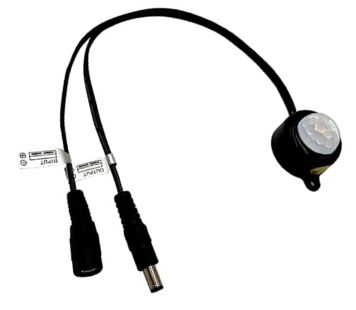
It determines when the door will open & close. If the relay is the heart then the light sensor has to be the brain. It senses light and closes the circuit which in turn controls the relay. Location is important to consider so the mounting location needs to be where it will best sense the sunlight. Ours is mounted on the SW corner of our barn to allow the coop door to stay open longer giving the chickens more time to return to the coop.
Link to Light sensor.
Power Options
There are basically two options for powering the circuitry and devices. One option is an AC adaptor providing the 12 volts DC, and the other is a 12 volt battery. We’ve set ours up to have the option of using an AC adaptor and 12 volt tool battery with a switch to change from one to the other. A solar setup is planned and may be a future update to this article, or part of a future article with other various options.
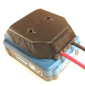
For now the two power options we have are working fine. Connection to the battery is accomplished with a battery power adapter. It’s a 3D printed component from Amazon and is battery specific. Others are available for different makes and voltages of power tool batteries.
Link to battery adapter.
Higher voltage batteries are also an option with the addition of a voltage converter. The link below is a 24V to 12V DC voltage reducer which worked fine with an 18V battery. It’s listed here as an option but is not part of our final build at this point. Link to voltage converter.
Protecting The Circuitry
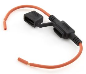
We went with an automotive universal fuse holder. Vehicles use 12 volts DC and so does this design. It simplifies things to use this setup or something similar from an automotive parts supplier. Ours came from our local auto parts store. It’s fused with a 2 amp fuse (sold separately).
Protecting The Battery
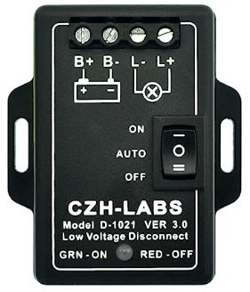
If a solar setup is used then the charge controller should protect the battery. If using a cordless tool battery then a low voltage disconnect is needed as a way to prevent the battery voltage from being drawn down too low and ruining the battery.
Link to low voltage disconnect.
Putting The Electrical Components Where They Belong
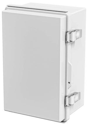
The electrical components are housed in an ABS plastic 11.8″x7.9″x6.7″ enclosure. This turned out to be a good size for the needed components as well as a few options. A smaller enclosure could be used if different power options are used or possibly re-arranging some components.
Note that some of the boxes on Amazon show a perforated backplate. The used for this build has a solid backplate. It works fine but drilling holes is required.
Link to project box.
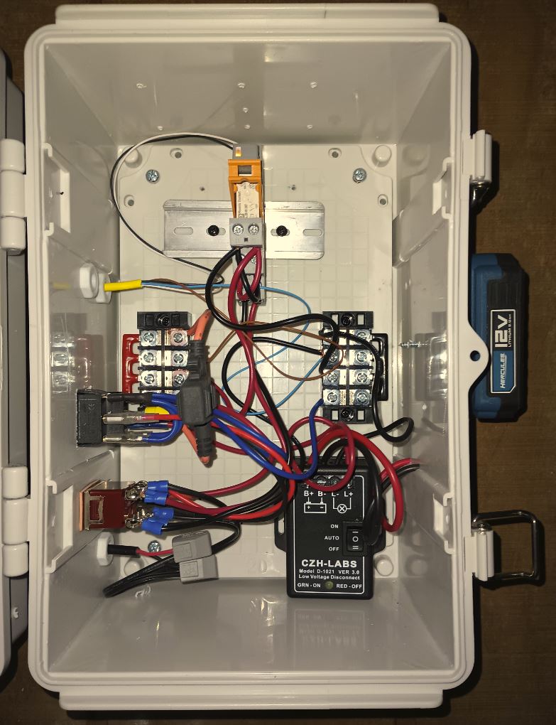
This arrangement of components worked out okay but getting all the wires to not look like a jumbled mess takes a little time and moving wires around. This is certainly not professional panel builder quality but it works and once the enclosure door is closed it looks great.
Check Your Work
Once all the electrical components are installed and wired it’s time to check functionality. Double check the wiring and anytime a wire needs to be moved or an electrical device changed remove the 12 volt power.
The actuator and light sensor aren’t part of the electrical box build so they will have to be connected temporarily. Once 12 VDC power is applied the actuator should move to the extended position even without the light sensor connected. The light sensor’s purpose is to energize the relay but if it’s not there the relay isn’t energized and the actuator should move to the extended (door closed) position. If it doesn’t the polarity may be backwards and the two actuator wire connections should be swapped.
Once this is functional connect the light sensor (remove power first). Once connected, reconnect power and the relay should energize and the actuator should move to the retracted (door open) position. Covering an uncovering the light sensor should make the actuator extend and retract. It’s best to make sure all the electrical is working before moving on the the installation and mechanical connections.
The Mechanical Setup
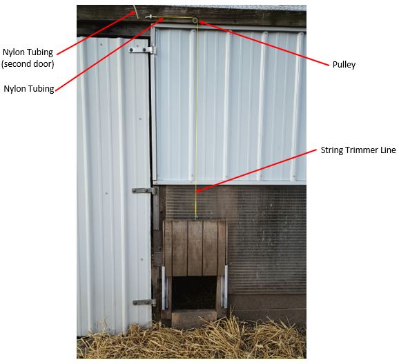
Once the control box is wired and the actuator connected electrically, the rest of the setup is mechanical. As mentioned earlier we’re using a flexible connection from the linear actuator to the coop door. The old manual setup we had worked fine with string trimmer line. We’re currently using the same for this automatic setup. I’m considering changing to a to a flexible stainless steel 1/16th diameter cable. The additional bends in this setup may stretch the nylon line over time and we will update this article if that change is made. For the trimmer line I’d recommend something high quality with a round profile.
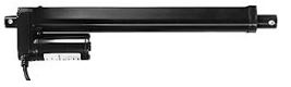
The linear actuator is the link between the electrical controls and the mechanical movement. The length of the stroke will determine how high the door will lift. We’re using a 12″ actuator.
Link to 12″ actuator.
Coming out of the barn is a short section of nylon tubing with the nylon trimmer line inside. This provides a low friction workable radius to ease the sharp 90° turn. The pulley is mounted directly above the chicken coop door and translates the line horizontal motion to a vertical motion.
Done
This is a welcomed little project that was fun to build as well as to enjoy on a daily basis by saving someone, usually me, trips to the chicken coop after dark. This is a fairly new addition to our little homestead and is still being proven out. Updates will be provided as necessary. There are a few options mentioned in this article that are being developed and tweaked and are planned as a follow-up article.
Below is the materials list and links to online resources. The main, necessary, components are listed above. The ones below may not be necessary but they are convenient and do make the work easier
Materials List
The major components are listed with links within the article above. Below is a summary:
- Electrical enclosure, 11.8″x7.9″x6.7″
- Control relay, 12 volt DC, DPDT, 8 amp
- Light sensor
- Battery adapter
- Battery low voltage protection
- Fuse holder
- Fuse, 2 amp
- Linear actuator, 12vdc, 12″ stroke, 1000 newton force rating, (about 225 pounds)
- 12 volt cordless tool battery (Hercules brand in our case)
- AC adapter, 12vdc, 1.2 amp (just something I had on hand but there are many similar ones on Amazon and elsewhere)
Also nice to have…
Various electrical connectors. This one from Walmart worked out well but there are lots of these available both locally and online. Link to connectors.
Wire splice with lever. These basically replace wire nuts and work great. Link to splice
5.5×2.1mm 2 Pins DC Power Jack Female Panel Mounting Connector Socket. Used to connect the AC adaptor if you use this as a power source. Link to power jack.
12V DC Power Connector 5.5mm x 2.1mm. These work well to connect the light sensor which has compatible connectors already installed on its connection wires. Link to power connectors.
Cable Gland Kit. This kit has an assortment of sizes and we used a few of the smallest ones to get cables through the enclosure wall. Link to cable gland kit.
Terminal block for power distribution. Used as a common landing point for the +12 volt DC and 0 volt DC. Some of the wire splices could also be used for this. Link to terminal block power distribution.
Various… screws, zip ties, shrink tube and anything else you can think of to assist in the project.